- 您现在的位置:买卖IC网 > Sheet目录116 > U30DCT-E3/4W (Vishay General Semiconductor)DIODE 30A 200V 25NS DUAL TO220-3
New Product
U(B)30BCT thru U(B)30DCT
Vishay General Semiconductor
Document Number: 89015
Revision: 27-Aug-08
For technical questions within your region, please contact one of the following:
PDD-Americas@vishay.com, PDD-Asia@vishay.com, PDD-Europe@vishay.com
www.vishay.com
925
Dual Common-Cathode Ultrafast Plastic Rectifier
FEATURES
? Oxide planar chip junction
Ultrafast recovery time
Soft recovery characteristics
Low switching losses, high efficiency
High forward surge capability
Meets MSL level 1, per J-STD-020, LF maximum
peak of 245 °C (for TO-263AB package)
Solder dip 260 °C, 40 s (for TO-220AB package)
Component in accordance to RoHS 2002/95/EC
and WEEE 2002/96/EC
TYPICAL APPLICATIONS
For use in low voltage, high frequency rectifier of
switching power supplies, freewheeling diodes,
dc-to-dc converters or polarity protection specifically
for CCM application.
MECHANICAL DATA
Case: TO-220AB and TO-263AB
Epoxy meets UL 94V-0
flammability rating
Terminals:
Matte tin plated leads, solderable per
J-STD-002 and JESD22-B102
E3 suffix for consumer grade, meets JESD 201 class
1A whisker test
Polarity:
As marked
Mounting Torque:
10 in-lbs maximum
PRIMARY CHARACTERISTICS
IF(AV)
2 x 15 A
VRRM
100 V, 150 V, 200 V
IFSM
160 A
trr
17 ns
VF
at I
F
= 15 A 0.892 V
TJ max. 150 °C
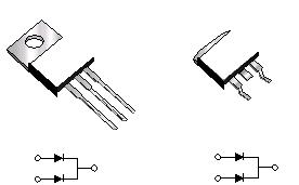
CASE
PIN 2
PIN 1
PIN 3
TO-220AB
U30xCT
UB30xCT
K
PIN 1
PIN 2 HEATSINK
1
32
1
2
K
TO-263AB
MAXIMUM RATINGS (TC
= 25 °C unless otherwise noted)
PARAMETER SYMBOL U(B)30BCT U(B)30CCT U(B)30DCT UNIT
Maximum repetitive peak reverse voltage VRRM
100 150 200 V
Max. average forward rectified current
(Fig. 1)
total device
per diode
IF(AV)
30
15
A
Peak forward surge current single half sine-wave
superimposed on rated load per diode
8.3 ms
10 ms
IFSM
160
150
A
Electrostatic discharge capacitor voltage,
human body model: C = 150 pF, R = 1.5 kΩ
(contact mode)
VC
8kV
Operating junction and storage temperature range TJ, TSTG
- 55 to + 150 °C


发布紧急采购,3分钟左右您将得到回复。
相关PDF资料
UB10DCT-E3/8W
DIODE 10A 200V 20NS DUAL
UB16DCT-E3/8W
DIODE 16A 200V 35NS DUAL
UG30DPT-E3/45
DIODE 30A 200V 20NS DUAL TO3P-3
UGB10DCTHE3/81
DIODE 10A 200V 20NS DUAL UF
UGB18DCTHE3/81
DIODE 18A 200V 20NS DUAL UF
UGF8JCTHE3/45
DIODE 8A 600V 25NS DUAL TO220-2
UH4PDCHM3/86A
DIODE 4A 200V 25NS DUAL TO277A
UHF20FCT-E3/4W
DIODE 20A 300V 25NS DUAL TO220-3
相关代理商/技术参数
U30FWJ2C48M
制造商:Toshiba America Electronic Components 功能描述:SCHOTTKY 30V 30A 3PIN TO-220SM - Rail/Tube
U30FWJ2C48M(T24L,Q
功能描述:肖特基二极管与整流器 Diode Schottky Center Tap 30V 30A RoHS:否 制造商:Skyworks Solutions, Inc. 产品:Schottky Diodes 峰值反向电压:2 V 正向连续电流:50 mA 最大浪涌电流: 配置:Crossover Quad 恢复时间: 正向电压下降:370 mV 最大反向漏泄电流: 最大功率耗散:75 mW 工作温度范围:- 65 C to + 150 C 安装风格:SMD/SMT 封装 / 箱体:SOT-143 封装:Reel
U30GWJ2C48C
制造商:TOSHIBA 制造商全称:Toshiba Semiconductor 功能描述:SWITCHING MODE POWER SUPPLY APPLICATON
U30GWJ2C48C(TE24R)
制造商:Toshiba America Electronic Components 功能描述:SCHOTTKY 40V 30A 3PIN TO-220SM - Tape and Reel
U30GWJ2C48CTE24R
制造商:Toshiba America Electronic Components 功能描述:SCHOTTKY 40V 30A 3PIN TO-220SM - Tape and Reel
U30GWJ2C53C
制造商:TOSHIBA 制造商全称:Toshiba Semiconductor 功能描述:Switching Mode Power Supply Application Converter&Chopper Application
U30P
功能描述:机架和机柜 11-1/4 x 12 x 6 GRAY W/CLEAR DRAWERS RoHS:否 制造商:Hammond Manufacturing 产品:Racks 类型:Table Top 外部宽度: 外部高度: 外部深度: 面板高度: 面板宽度:
U30P-C
功能描述:存储箱与外壳 11-1/4 x 12 x 6 (2.209cf) RoHS:否 制造商:Tektronix 颜色:Black 材料:Polypropylene 尺寸:23.25 in L x 20.75 in W x 9 in H
